Best Result Digital Direct Shear Apparatus
VSLIC-S131
Copyright @2023 Vertex Group
Copyright @2023 Vertex Group
short info
This Digital Direct Shear Test Apparatus it similar to VSLIC-S131 but excerpt that it can accommodate sample size of 300*300*150 mm. Servomotor can create power to give a shearing load of 50kN. Additional Stepper motor is provided for normal stress. This stepper motor can create a maximum stress of 5kg/sqcm. Total controlling is through the computer. Parameters like shearing load, vertical strain and horizontal strain is shown on the monitor.
Standard
IS: 2720 (Part XXXIX/Sec. I)
Model
VSLIC-S131
Origin
Indian
Make/ OEM
VERTEX
Warranty
This Warranty covers the defects resulting from defective parts, materials or manufacturing, if such defects are revealed during the period of 12 months since the date of purchase.
Picture
All pictures shown are for illustration purpose only. actual product may vary due to product enhancement.
This Digital Direct Shear Test Apparatus it similar to VSLIC-S131 but excerpt that it can accommodate sample size of 300*300*150 mm. Servomotor can create power to give a shearing load of 50kN. Additional Stepper motor is provided for normal stress. This stepper motor can create a maximum stress of 5kg/sqcm. Total controlling is through the computer. Parameters like shearing load, vertical strain and horizontal strain is shown on the monitor.
Operation is based on the close loop Principle the specimen to be sheared can be loaded either on strain basis or stress basis.
Selection of this mode has to be made at the beginning of the test. Maximum strain rate that can be achieved is 9.9999mm/min where as the minimum strain rate could be programmed as low as 0.0001mm/min.
Loading System
For Horizontal strain controlled through micro stepper motor:
Rate of strain : 0.0001-9.9999mm/min.
Load range capacity : ± 50kN
Displacement range : ±50mm
For Vertical Consolidation:
Capacity : 5kg/cm2
Range : 0-20 mm
Electronic Sensors
Load cell Universal type : 50kN
Displacement sensor horizontal : ±50mm
Displacement sensor vertical : ±50mm
Salient Features of software and graphical plots
It is supported by user-friendly windows based software for graphical plotting and numerical tabulations.
Horizontal displacement vs. Vertical displacement
Normal stress vs. Shear stress
Displays maximum value of dilation angle along with c and ø values.
FEATURES
This Digital Direct Shear Test Apparatus it similar to VSLIC-S131 but excerpt that it can accommodate sample size of 300*300*150 mm. Servomotor can create power to give a shearing load of 50kN. Additional Stepper motor is provided for normal stress. This stepper motor can create a maximum stress of 5kg/sqcm. Total controlling is through the computer. Parameters like shearing load, vertical strain and horizontal strain is shown on the monitor.
Operation is based on the close loop Principle the specimen to be sheared can be loaded either on strain basis or stress basis.
Selection of this mode has to be made at the beginning of the test. Maximum strain rate that can be achieved is 9.9999mm/min where as the minimum strain rate could be programmed as low as 0.0001mm/min.
Loading System
For Horizontal strain controlled through micro stepper motor:
Rate of strain : 0.0001-9.9999mm/min.
Load range capacity : ± 50kN
Displacement range : ±50mm
For Vertical Consolidation:
Capacity : 5kg/cm2
Range : 0-20 mm
Electronic Sensors
Load cell Universal type : 50kN
Displacement sensor horizontal : ±50mm
Displacement sensor vertical : ±50mm
Salient Features of software and graphical plots
It is supported by user-friendly windows based software for graphical plotting and numerical tabulations.
Horizontal displacement vs. Vertical displacement
Normal stress vs. Shear stress
Displays maximum value of dilation angle along with c and ø values.
PRODUCT VIDEO
WORKING PRINCIPALNew
Shear Strength of Soil by Direct Shear Test
Shear strength of a soil is its maximum resistance to shearing stresses. The shear strength is expressed as
Where C’ = Effective cohesion
= Effective stress = Effective angle of shearing resistance
Using direct shear test, one can find out the cohesion and angle of internal friction of soil which are useful in many engineering designs such as foundations, retaining walls, etc.
This test can be performed in three different drainage conditions namely unconsolidated-undrained, consolidated-undrained and consolidated-drained conditions. In general, cohesionless soils are tested for direct shear in consolidated drained condition.
Apparatus Required for Direct Shear Test
Apparatus required for conduction direct shear test are
Shear box
Shear box container
Base plate with cross groves on its top
Porous stones (2 Nos)
Plain Grid plates (2Nos)
Perforated grid plates (2Nos)
Loading pad with steel ball
Digital weighing machine
Loading frame with loading yoke
Proving ring
Dial gauges (2 Nos)
Weights
Tampering Rod
Spatula
Rammer
Sampler
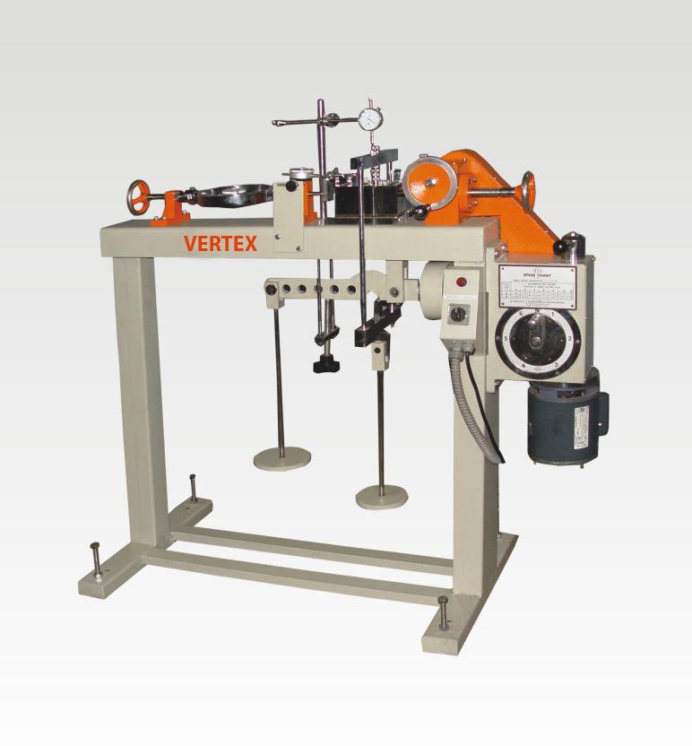
Fig 1: Direct Shear Test Apparatus
Test Procedure of Direct Shear Test
Test Procedure of Direct shear test contains following steps:
Collect the soil specimen which is either undisturbed or remolded. The sample should be taken using sampler and Rammer. If cohesionless soil is taking then sampler and rammer are not required.
The inner dimensions of sampler should be 60 mm x 60 mm in plan which are also the inner dimensions of shear box. The Thickness of box is about 50 mm while the thickness of sample should be 25mm.Fig 2: Shear Box,Porous Stones, Grid Plates, Loading pad
Now attach the two halves of the shear box with locking pins and place the base plate at the bottom.
Above the bottom plate, Place the porous stone and above it place the grid plate. Plain grid plates are used for undrained conditions while perforated grid plates are used for drained conditions.
Now we have baseplate, porous stone and grid plate in the shear box. Weigh the box at this stage and note down.
After that place the soil specimen above the grid plate. Undisturbed sample is directly transferred to shear box. If sandy soil is using, place it layers wise and tamper the each layer to get the required density.
Note down the weight of shear box with soil specimen.
Above the soil specimen, place the upper grid plate, porous stone and loading pad one above the other.Fig 3: Different Layers Positions in Shear Box
Now the whole box is placed in a container and mounted on the loading frame.
Proving ring is arranged in such a way that it should contact the upper half of the shear box.
Loading yoke is placed on the steel ball of loading pad of shear box.
Two dial gauges are fitted one to the container for measuring shear displacement and other one is to the loading yoke for measuring vertical displacement.
Now locking pins are removed from the shear box and spacing screws are placed in their respective positions of the box.Fig 4: Applying Load on Specimen
The upper half of the box is raised slightly with the help of spacing screws. The spacing is decided depending upon the maximum size of particle.
Now apply the normal stress which is generally 25 kN/m2. Also apply the shear load at a constant rate of strain.
Now the box starts reacting to loads applied and for every 30 seconds note down the readings of proving ring and dial gauges.
If the proving ring reaches maximum and suddenly drops it, means the specimen is failed. Note down the maximum value which is nothing but failure stress.
For some soils, failure point is taken at 20% of shear strain.
Finally remove the box and measure the water content of the specimen.
Repeat the same procedure for different normal stresses of 50, 100, 150,200,250,300,400 kN/m2
Observations and Calculations for Direct Shear Test
Calculations are to be done using the observations taken from the test as follows:
Size of the box =
Area of the box =
Thickness of specimen =
Mass of specimen =
Volume of specimen =
Bulk Density of soil =
Dry density of soil =
Void ratio =
Mass of box + base plate + porous stone + grid plate =
Mass of box + base plate + porous stone + grid plate + Soil specimen =
Calculate the shear stress using below tabulated observations:
S.No
Elapsed time
Horizontal dial gauge reading
Horizontal displacement
Vertical dial gauge reading
Vertical displacement
Proving ring reading
Shear force
Shear stress
Now determine the shear stress at failure for different normal stress values:
Test no.
Normal stress(kN/m2)
Shear Stress at Failure (kN/m2)
Shear Displacement at Failure
Initial Water Content
Final Water Content
Now plot a graph between normal stress and shear stress by taking normal stress on abscissa and shear stress at failure on ordinate. The graph looks like as shown below.
Fig 5: Graph plotted between Normal Stress and Shear stress
From the graph cohesion intercept (c’) and angle of shearing resistance () can be known and shear strength (s) can be calculated from the formula.
Result of Direct Shear Test
Shear strength of the given soil sample is = ______________ kN/m2.
Get Instant Quote
Our Hot Selling Instrument's
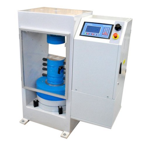
Servo Fully Automatic Compression Testing Machine
One of the key advantages of the SERVO CONTROLLED FULLY AUTOMATIC COMPRESSION TESTING MACHINE is its ability to deliver highly accurate results. This precision ensures that your materials meet the required standards, reducing the risk of costly errors and rework. Moreover, by producing consistent and reliable outcomes, you build a reputation for quality in your industry.
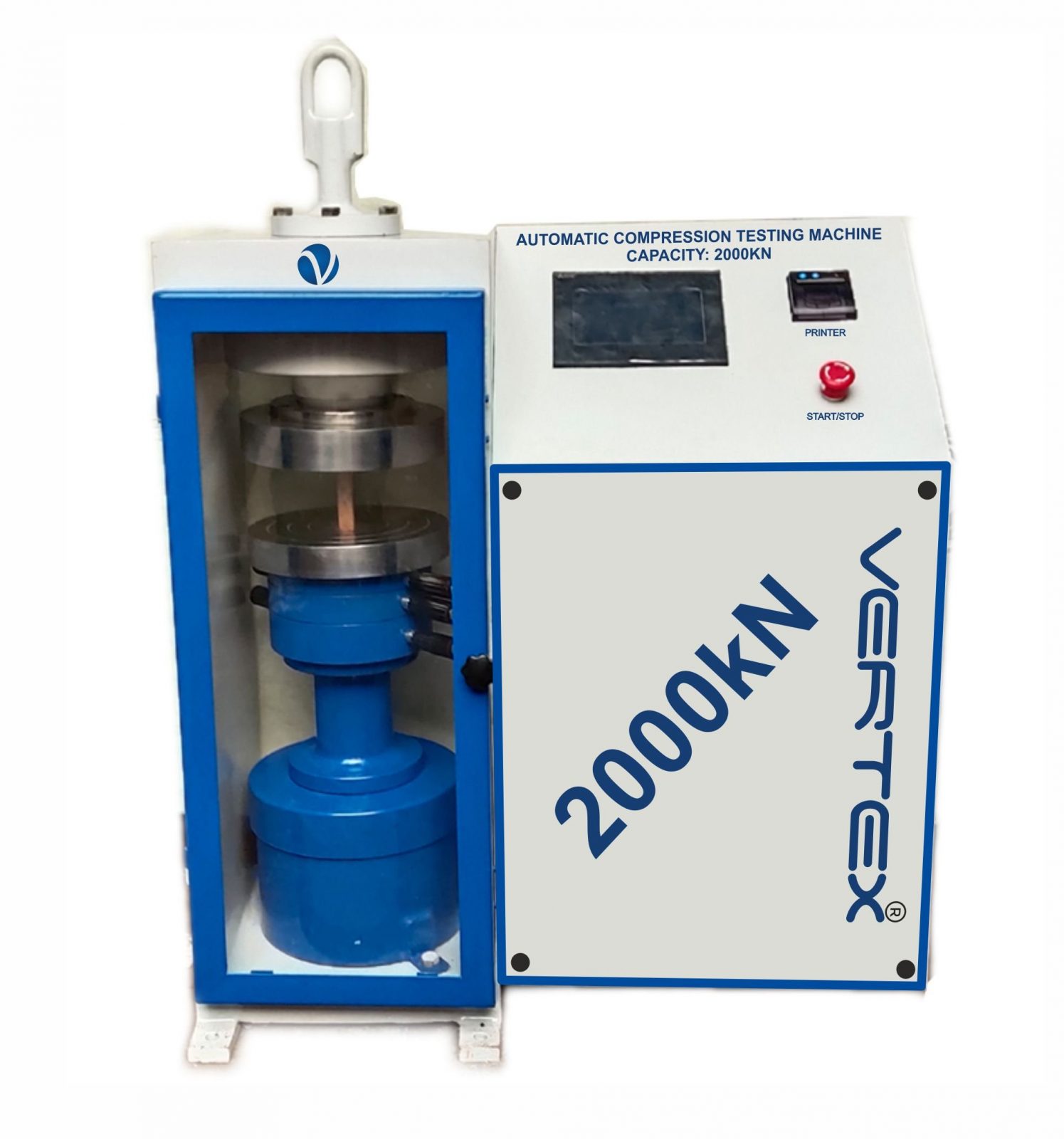
Automatic Compression Testing Machine
Manufactured as per International design, Plate model for highest mechanical stability, accurate centering of load and excellent repeatability. Fully Automatic pace rate control, auto stop and auto release on failure of test specimen, can be attached with flexural load frame or 500 KN load frame.
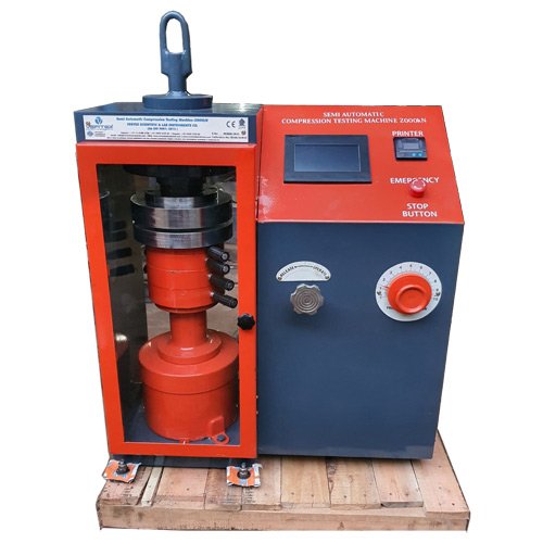
Semi Automatic Compression Testing Machine
Pace rate is achieved manually by controlling the flow control knob and the adjustment can be made by observing the error on the display and the system is released manually after the peak load is achieved.
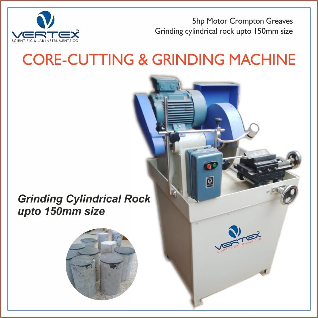
Rock Core Cutting & Grinding Machine
Rock Cutting Machine can be used to cut cores of varied sizes of concrete, stones, other building materials and metallic specimens.