short info

  • Conforming to Testing Procedures laid down in IS/ASTM for testing of rock specimens
  • Suitable to conduct Triaxial Test, Unconfined, Indirect Tensile, Creep Tests and normal Compression Tests on Rock specimen up to NX size in both Cyclic (Frequency Range-0.01Hz-10Hz) and Routine Static testing
  • Based on SERVO HYDRAULIC CLOSED LOOP FEEDBACK mechanism Fully Automated controlled Axial Loading in Load/Stress and Displacement basis in both Cyclic and Static Testing with User friendly Software

Model

VSLIC-R120

Origin

Indian

Make/ OEM

VERTEX

  • Description

  • SPECIFICATIONS

  • FEATURES

  • VIDEO
  •  New
    WORKING PRINCIPAL

OVERVIEW

Salient Features

  • Conforming to Testing Procedures laid down in IS/ASTM for testing of rock specimens
  • Suitable to conduct Triaxial Test, Unconfined, Indirect Tensile, Creep Tests and normal Compression Tests on Rock specimen up to NX size in both Cyclic (Frequency Range-0.01Hz-10Hz) and Routine Static testing
  • Based on SERVO HYDRAULIC CLOSED LOOP FEEDBACK mechanism Fully Automated controlled Axial Loading in Load/Stress and Displacement basis in both Cyclic and Static Testing with User friendly Software
  • Stable, robust Loading Unit (Capacity up to 4000kN) that can accommodate Triaxial cell up to Nx Size specimen
  • Digitally controlled High Pressure Controller (Pressure Ranges 0.5- 100 MPa) based on Closed loop principle to maintain Cell pressure
  • High Pressure Triaxial Cell to accommodate Sample size range from Ex to Nx with L:D ratio 1:2 (With maximum pressure up to 100MPa)
  • High speed measurement and data acquisition through advanced electronics
  • Facility to study Post failure behaviors of specimens• Programmable Sample Parameters and machine controlling parameter
  • Auto release facility after specimen failure
  • Online Plotting of Graphs (Load v/s Displacement, Load v/s Time, Displacement v/s Time) with display of data
  • Supported by highly Advanced User friendly Application software for conducting tests and for analysis of test results
  • Safety Limits Over Load & Over Displacement

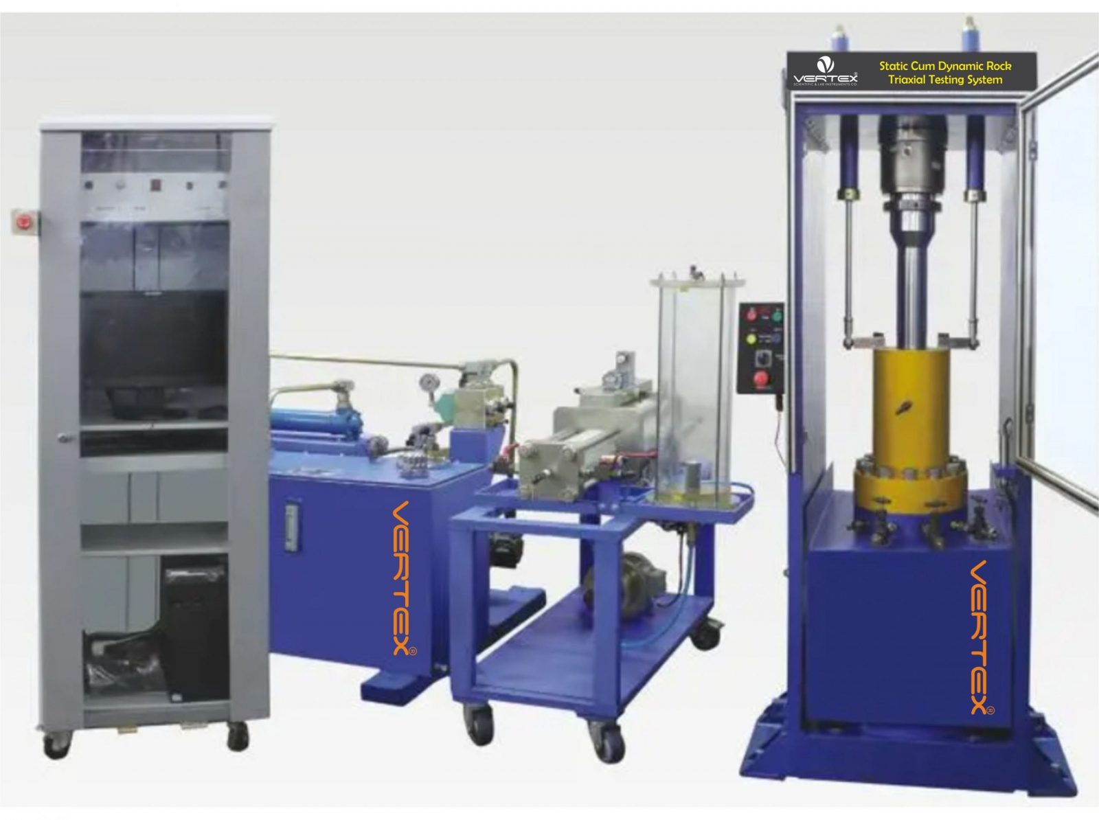
The complete system comprises of followings:-

  • Stiff Frame
  • Hydraulic Power Pack
  • Digital High Pressure Controller
  • High Pressure Triaxial Cell
  • PC based Control system and Control Software

1. Stiff Frame 

The system is a totally welded structure, which gives a tremendous amount of stability to the system. It has an equal area hydraulic cylinder attached to the base and an oil filled spherical seating is screwed to the top with Solid platen having hardness greater than 45-50HRC. The horizontal and vertical clearances are enough to test standard rock specimen under triaxial test. It can accommodate a triaxial cell with a sample size up to 90 mm size. Front cover is provided, made of acrylic sheet, as a protection to the operator while at the same time giving an unobstructive view of the specimen under test.

  • Loading Capacity of the unit
  • (Static & Dynamic) : 1000/2000kN
  • Total travel of the ram : 50mm
  • Clearance – Horizontal : 450mm
  • Vertical : 820mm
  • Platen Size : 250mm

2. High Pressure Triaxial Cell 

The unit consists of metallic high pressure chamber. A hardened, ground and lapped frictionless plunger passes through the removable head. The cylinder is clamped to a base plate having four drilled take off positions for measurement of lateral pressure, pore pressure, back pressure and top drainage. The specimen pedestal and loading pads are also hardened. Spherical seating is provided at the top of the specimen loading pad for self alignment. Triaxial cell is suitable for specimen size ranging from Ex to Nx. Four sets of pedestals (Ex, Ax, Bx & Nx) are provided as standard along with the unit. Side jacks are also provided for lifting the cover of Triaxial cell.

Triaxial Cell has arrangement for taking out electrical leads of strain gauges pasted on the specimen.

MODEL : PRESSURE RANGE

  • 0 – 7MPa
  • 0 – 15MPa
  • 0 – 35MPa
  • 0 – 50MPa
  • 0 – 70MPa
  • 0 – 100MPa

3. Hydraulic Power Supply

Hydraulic power supplies are compact in design and are suitable for the supply of required flow and pressure for the movement of the actuator. It has an oil tank of adequate capacity, vane type pump powered by a three phase motor. All the electrical controls including the temperature controller are fixed on one side of the tank. It includes all the accessories like pressure line filter, return line filter, oil level, relief valve, pressure gauge and shell & tube type heat exchanger. Anti vibration mountings are provided as standard along with the HPS. Cooling system for keeping oil within working temperature range is provided as standard. The system is kept at a distance from the loading unit and connected through flexible pipes.

Technical Specification

  • Flow of the pump : 40LPM
  • Motor capacity : 25HP
  • Capacity f the tank : 200litres
  • Operating pressure : 200Bars

NOTE – System will be supplied with necessary cable and fittings for the operation of the machine and machine operates on 440VAC 3 phase supply.

4. Digital High Pressure Controller

The Controllers are designed to maintain confining pressure at the set value with the help of servo valve based on PID closed loop feedback principle. Sensing back is from a sensitive pressure transducer. Pressure is maintained with in the range of +2 % irrespective of any deformation that takes place during testing of the specimen. A series of relays are provided for automatic actuation of the main pumping unit depending upon the volume change in the specimen. This unit can be operated by the same hydraulic power pack.

Model : Pressure Gauge

  • 0.1 – 7MPa
  • 0.2 – 15MPa
  • 0.5 – 35MPa
  • 0.5 – 50MPa
  • 0.5 – 70MPa
  • 0.5 – 100MPa

5. PC Control System & Control Software

Control system provides the digital servo control, Wave generation for the axial loading, data acquisition, hydraulic control etc. for the continuous operation of the system.

(a) Signal Conditioning & Controlling Unit VERTEX Servo controller basically consists of signal conditioning unit and controlling unit. Signal conditioning unit consists of conditioning modules for various transducers (e.g. Load Cell, Displacement Transducers etc.) that receives the output signal from these sensors and amplifies and process that signal as per the requirement and transfer it to computer through dedicated cables where it is accepted by the data acquisition system. The out put from the signal conditioning unit for each transducers range from 0-5V.The controlling unit controls the movement of the RAM with respect to the signal input on feed back basis either from LOAD CELL or DISPLACEMENT sensor.

It consists of dedicated servo-controller card that gives the desired processed signal through the P.I.D controller to the servo valve to operate either of the control modes i.e. Load mode or  Displacement mode. It also sends the signal to computer and accepts the command from the software to operate in desired manner. The system can generate sine, triangular or square wave form and also can accept external input wave form as generated in the field. The programming facility is given to operate the system in STATIC MODE at programmed rate of loading in both Load and Displacement controls. In DYNAMIC MODE the cycling can be done at a frequency from 0.01Hz-10Hz or even higher.

Specifications of Controller

  • Auto PID operation with auto loop shaping servo operation
  • Closed loop update rate is 10 kHz
  • No. of control channels- 2 (Load/Displacement)
  • Demand Wave generation – Sine, Triangular, Square, Random wave forms and Ramp signal
  • High speed Data Acquisition card with 100 kHz sampling rate and 16-bit resolution acquires data from the signal conditioning and controlling unit
  • System accuracy – Load accuracy : ±0.5% of indicated value of Load Displacement accuracy: ± 0.5% of indicated value
  • Two types of Loading – Dynamic (for fatigue test) and Static (Ramp)
  • Dynamic Frequency Range – 0.01Hz to 10Hz or even higher (Note: The stroke of actuator depends upon the frequency of operation. Performance curve will be provided along with the offer)
  • Static Ramp rate: Load control mode – 1kN/sec – 10kN/sec Displacement control mode- 0.001mm/sec – 2mm/sec.
  • Environmental Temperature – 0OC to + 60OC
  • Relative Humidity – 10% to 85% noncondensing
  • Supply Input – 220-240 VAC, 50 Hz

(b) Computer for Controlling and Data acquisition System is provided with dedicated computer of latest available configuration with built in data acquisition card and wave generator.

Data acquisition card

The PCI Bus advanced data acquisition card provides the following advanced features

  • 32 bit PCI- bus
  • 16-bit Analog Input resolution (Higher bit resolution up to 24bit)
  • Auto Scanning Channel selection up to 16 channels.

Up to 100 KHz A/D Sampling Rates

  • 16 Single ended Analog Input channels
  • Bipolar Input signals
  • Programmable gain of x1, x2, x4, x8, x16
  • Input range: +/-10V, +/-5V, +/-2.5 V, +/- 1.25V, +/-0.625V
  • One 12-bit Monolithic multiplying Analog Output channel
  • 16 Digital Output and 16 Digital Input channels
  • 4 extended Digital Input and Digital Output channels on the 37 – pin con nector
  • 3 Independent programmable 16-bit down| counters.
  • Three A/D Trigger modes: Software Trigger, Programmable Pacer Trigger and External Pulse Trigger
  • Pre-trigger control
  • Internal DC-to-DC converter for stable Analog power source.

Control Software

Controlling and On-line Data Acquisition to PC through user friendly software and Statistical Analysis of the results obtained.

Salient Features

  • Windows based user friendly software
  • Capable of testing Triaxial Test, Unconfined, Indirect Tensile, Creep Tests and normal Compression Tests on Rock specimen up to NX size in both Cyclic (Frequency Range-0.01Hz-10Hz) and Routine Static testing
  • Four different types of axial loading can be given to the sample- Sine, Square, Triangle and Ramp signal
  • Programmable Loading parameters – Frequency, Base, Amplitude etc.
  • Programmable rate of loading in Static Tests
  • Programmable cell pressure and automatic controlling of cell pressure
  • Computer/Software programmable Safety Limits for each load & displacement
  • Independent Taring of each channel
  • Facility to hold the loading and restart loading during the test.
  • Shows number of cycle on screen
  • Store the number of cycles in Dynamic test
  • Real time display of Load v/s Displacement, Load v/s Time & Displacement v/s Time graphs
  • On-line display of load, displacement and Confining pressure
  • Auto adjustment of graph scales

Analysis Software

  • Plotting of following graphs a Load v/s Time

b) Displacement v/s Time

c) Load v/s Displacement

d) Stress v/s Strain

  • Calculation of various results (Young’s modulus, Maximum strain, Compressive Strength etc.)
  • Facility to plot the data for a selected run
  • Comparative analysis using multi graphs
  • Statistical analysis of the test results
  • Batch Summary Report
  • Detailed Summary Report
  • Advance Statistical Analysis
  • Facility to print Test Reports
  • Facility to Export Data to MS Excel

Combined Electronic Axial Compressometer & Lateral Extensometer for Nx size Sample

This unit is essentially used for finding out poises ratio of rocks specimen. It has displacement sensors both for lateral extension and for compression.

Total displacement is ± 2mm with sensitivity of 0.001 mm. Complete with digital display.


SPECIFICATIONS

Salient Features

  • Conforming to Testing Procedures laid down in IS/ASTM for testing of rock specimens
  • Suitable to conduct Triaxial Test, Unconfined, Indirect Tensile, Creep Tests and normal Compression Tests on Rock specimen up to NX size in both Cyclic (Frequency Range-0.01Hz-10Hz) and Routine Static testing
  • Based on SERVO HYDRAULIC CLOSED LOOP FEEDBACK mechanism Fully Automated controlled Axial Loading in Load/Stress and Displacement basis in both Cyclic and Static Testing with User friendly Software
  • Stable, robust Loading Unit (Capacity up to 4000kN) that can accommodate Triaxial cell up to Nx Size specimen
  • Digitally controlled High Pressure Controller (Pressure Ranges 0.5- 100 MPa) based on Closed loop principle to maintain Cell pressure
  • High Pressure Triaxial Cell to accommodate Sample size range from Ex to Nx with L:D ratio 1:2 (With maximum pressure up to 100MPa)
  • High speed measurement and data acquisition through advanced electronics
  • Facility to study Post failure behaviors of specimens• Programmable Sample Parameters and machine controlling parameter
  • Auto release facility after specimen failure
  • Online Plotting of Graphs (Load v/s Displacement, Load v/s Time, Displacement v/s Time) with display of data
  • Supported by highly Advanced User friendly Application software for conducting tests and for analysis of test results
  • Safety Limits Over Load & Over Displacement

The complete system comprises of followings:-

  • Stiff Frame
  • Hydraulic Power Pack
  • Digital High Pressure Controller
  • High Pressure Triaxial Cell
  • PC based Control system and Control Software

1. Stiff Frame 

The system is a totally welded structure, which gives a tremendous amount of stability to the system. It has an equal area hydraulic cylinder attached to the base and an oil filled spherical seating is screwed to the top with Solid platen having hardness greater than 45-50HRC. The horizontal and vertical clearances are enough to test standard rock specimen under triaxial test. It can accommodate a triaxial cell with a sample size up to 90 mm size. Front cover is provided, made of acrylic sheet, as a protection to the operator while at the same time giving an unobstructive view of the specimen under test.

  • Loading Capacity of the unit
  • (Static & Dynamic) : 1000/2000kN
  • Total travel of the ram : 50mm
  • Clearance – Horizontal : 450mm
  • Vertical : 820mm
  • Platen Size : 250mm

2. High Pressure Triaxial Cell 

The unit consists of metallic high pressure chamber. A hardened, ground and lapped frictionless plunger passes through the removable head. The cylinder is clamped to a base plate having four drilled take off positions for measurement of lateral pressure, pore pressure, back pressure and top drainage. The specimen pedestal and loading pads are also hardened. Spherical seating is provided at the top of the specimen loading pad for self alignment. Triaxial cell is suitable for specimen size ranging from Ex to Nx. Four sets of pedestals (Ex, Ax, Bx & Nx) are provided as standard along with the unit. Side jacks are also provided for lifting the cover of Triaxial cell.

Triaxial Cell has arrangement for taking out electrical leads of strain gauges pasted on the specimen.

MODEL : PRESSURE RANGE

  • 0 – 7MPa
  • 0 – 15MPa
  • 0 – 35MPa
  • 0 – 50MPa
  • 0 – 70MPa
  • 0 – 100MPa

3. Hydraulic Power Supply

Hydraulic power supplies are compact in design and are suitable for the supply of required flow and pressure for the movement of the actuator. It has an oil tank of adequate capacity, vane type pump powered by a three phase motor. All the electrical controls including the temperature controller are fixed on one side of the tank. It includes all the accessories like pressure line filter, return line filter, oil level, relief valve, pressure gauge and shell & tube type heat exchanger. Anti vibration mountings are provided as standard along with the HPS. Cooling system for keeping oil within working temperature range is provided as standard. The system is kept at a distance from the loading unit and connected through flexible pipes.

Technical Specification

  • Flow of the pump : 40LPM
  • Motor capacity : 25HP
  • Capacity f the tank : 200litres
  • Operating pressure : 200Bars

NOTE – System will be supplied with necessary cable and fittings for the operation of the machine and machine operates on 440VAC 3 phase supply.

4. Digital High Pressure Controller

The Controllers are designed to maintain confining pressure at the set value with the help of servo valve based on PID closed loop feedback principle. Sensing back is from a sensitive pressure transducer. Pressure is maintained with in the range of +2 % irrespective of any deformation that takes place during testing of the specimen. A series of relays are provided for automatic actuation of the main pumping unit depending upon the volume change in the specimen. This unit can be operated by the same hydraulic power pack.

Model : Pressure Gauge

  • 0.1 – 7MPa
  • 0.2 – 15MPa
  • 0.5 – 35MPa
  • 0.5 – 50MPa
  • 0.5 – 70MPa
  • 0.5 – 100MPa

5. PC Control System & Control Software

Control system provides the digital servo control, Wave generation for the axial loading, data acquisition, hydraulic control etc. for the continuous operation of the system.

(a) Signal Conditioning & Controlling Unit HEICO Servo controller basically consists of signal conditioning unit and controlling unit. Signal conditioning unit consists of conditioning modules for various transducers (e.g. Load Cell, Displacement Transducers etc.) that receives the output signal from these sensors and amplifies and process that signal as per the requirement and transfer it to computer through dedicated cables where it is accepted by the data acquisition system. The out put from the signal conditioning unit for each transducers range from 0-5V.The controlling unit controls the movement of the RAM with respect to the signal input on feed back basis either from LOAD CELL or DISPLACEMENT sensor.

It consists of dedicated servo-controller card that gives the desired processed signal through the P.I.D controller to the servo valve to operate either of the control modes i.e. Load mode or  Displacement mode. It also sends the signal to computer and accepts the command from the software to operate in desired manner. The system can generate sine, triangular or square wave form and also can accept external input wave form as generated in the field. The programming facility is given to operate the system in STATIC MODE at programmed rate of loading in both Load and Displacement controls. In DYNAMIC MODE the cycling can be done at a frequency from 0.01Hz-10Hz or even higher.

Specifications of Controller

  • Auto PID operation with auto loop shaping servo operation
  • Closed loop update rate is 10 kHz
  • No. of control channels- 2 (Load/Displacement)
  • Demand Wave generation – Sine, Triangular, Square, Random wave forms and Ramp signal
  • High speed Data Acquisition card with 100 kHz sampling rate and 16-bit resolution acquires data from the signal conditioning and controlling unit
  • System accuracy – Load accuracy : ±0.5% of indicated value of Load Displacement accuracy: ± 0.5% of indicated value
  • Two types of Loading – Dynamic (for fatigue test) and Static (Ramp)
  • Dynamic Frequency Range – 0.01Hz to 10Hz or even higher (Note: The stroke of actuator depends upon the frequency of operation. Performance curve will be provided along with the offer)
  • Static Ramp rate: Load control mode – 1kN/sec – 10kN/sec Displacement control mode- 0.001mm/sec – 2mm/sec.
  • Environmental Temperature – 0OC to + 60OC
  • Relative Humidity – 10% to 85% noncondensing
  • Supply Input – 220-240 VAC, 50 Hz

(b) Computer for Controlling and Data acquisition System is provided with dedicated computer of latest available configuration with built in data acquisition card and wave generator.

Data acquisition card

The PCI Bus advanced data acquisition card provides the following advanced features

  • 32 bit PCI- bus
  • 16-bit Analog Input resolution (Higher bit resolution up to 24bit)
  • Auto Scanning Channel selection up to 16 channels.

Up to 100 KHz A/D Sampling Rates

  • 16 Single ended Analog Input channels
  • Bipolar Input signals
  • Programmable gain of x1, x2, x4, x8, x16
  • Input range: +/-10V, +/-5V, +/-2.5 V, +/- 1.25V, +/-0.625V
  • One 12-bit Monolithic multiplying Analog Output channel
  • 16 Digital Output and 16 Digital Input channels
  • 4 extended Digital Input and Digital Output channels on the 37 – pin con nector
  • 3 Independent programmable 16-bit down| counters.
  • Three A/D Trigger modes: Software Trigger, Programmable Pacer Trigger and External Pulse Trigger
  • Pre-trigger control
  • Internal DC-to-DC converter for stable Analog power source.

Control Software

Controlling and On-line Data Acquisition to PC through user friendly software and Statistical Analysis of the results obtained.

Salient Features

  • Windows based user friendly software
  • Capable of testing Triaxial Test, Unconfined, Indirect Tensile, Creep Tests and normal Compression Tests on Rock specimen up to NX size in both Cyclic (Frequency Range-0.01Hz-10Hz) and Routine Static testing
  • Four different types of axial loading can be given to the sample- Sine, Square, Triangle and Ramp signal
  • Programmable Loading parameters – Frequency, Base, Amplitude etc.
  • Programmable rate of loading in Static Tests
  • Programmable cell pressure and automatic controlling of cell pressure
  • Computer/Software programmable Safety Limits for each load & displacement
  • Independent Taring of each channel
  • Facility to hold the loading and restart loading during the test.
  • Shows number of cycle on screen
  • Store the number of cycles in Dynamic test
  • Real time display of Load v/s Displacement, Load v/s Time & Displacement v/s Time graphs
  • On-line display of load, displacement and Confining pressure
  • Auto adjustment of graph scales

Analysis Software

  • Plotting of following graphs a Load v/s Time

b) Displacement v/s Time

c) Load v/s Displacement

d) Stress v/s Strain

  • Calculation of various results (Young’s modulus, Maximum strain, Compressive Strength etc.)
  • Facility to plot the data for a selected run
  • Comparative analysis using multi graphs
  • Statistical analysis of the test results
  • Batch Summary Report
  • Detailed Summary Report
  • Advance Statistical Analysis
  • Facility to print Test Reports
  • Facility to Export Data to MS Excel

Combined Electronic Axial Compressometer & Lateral Extensometer for Nx size Sample

This unit is essentially used for finding out poises ratio of rocks specimen. It has displacement sensors both for lateral extension and for compression.

Total displacement is ± 2mm with sensitivity of 0.001 mm. Complete with digital display.
FEATURES

Salient Features

  • Conforming to Testing Procedures laid down in IS/ASTM for testing of rock specimens
  • Suitable to conduct Triaxial Test, Unconfined, Indirect Tensile, Creep Tests and normal Compression Tests on Rock specimen up to NX size in both Cyclic (Frequency Range-0.01Hz-10Hz) and Routine Static testing
  • Based on SERVO HYDRAULIC CLOSED LOOP FEEDBACK mechanism Fully Automated controlled Axial Loading in Load/Stress and Displacement basis in both Cyclic and Static Testing with User friendly Software
  • Stable, robust Loading Unit (Capacity up to 4000kN) that can accommodate Triaxial cell up to Nx Size specimen
  • Digitally controlled High Pressure Controller (Pressure Ranges 0.5- 100 MPa) based on Closed loop principle to maintain Cell pressure
  • High Pressure Triaxial Cell to accommodate Sample size range from Ex to Nx with L:D ratio 1:2 (With maximum pressure up to 100MPa)
  • High speed measurement and data acquisition through advanced electronics
  • Facility to study Post failure behaviors of specimens• Programmable Sample Parameters and machine controlling parameter
  • Auto release facility after specimen failure
  • Online Plotting of Graphs (Load v/s Displacement, Load v/s Time, Displacement v/s Time) with display of data
  • Supported by highly Advanced User friendly Application software for conducting tests and for analysis of test results
  • Safety Limits Over Load & Over Displacement

The complete system comprises of followings:-

  • Stiff Frame
  • Hydraulic Power Pack
  • Digital High Pressure Controller
  • High Pressure Triaxial Cell
  • PC based Control system and Control Software

1. Stiff Frame 

The system is a totally welded structure, which gives a tremendous amount of stability to the system. It has an equal area hydraulic cylinder attached to the base and an oil filled spherical seating is screwed to the top with Solid platen having hardness greater than 45-50HRC. The horizontal and vertical clearances are enough to test standard rock specimen under triaxial test. It can accommodate a triaxial cell with a sample size up to 90 mm size. Front cover is provided, made of acrylic sheet, as a protection to the operator while at the same time giving an unobstructive view of the specimen under test.

  • Loading Capacity of the unit
  • (Static & Dynamic) : 1000/2000kN
  • Total travel of the ram : 50mm
  • Clearance – Horizontal : 450mm
  • Vertical : 820mm
  • Platen Size : 250mm

2. High Pressure Triaxial Cell 

The unit consists of metallic high pressure chamber. A hardened, ground and lapped frictionless plunger passes through the removable head. The cylinder is clamped to a base plate having four drilled take off positions for measurement of lateral pressure, pore pressure, back pressure and top drainage. The specimen pedestal and loading pads are also hardened. Spherical seating is provided at the top of the specimen loading pad for self alignment. Triaxial cell is suitable for specimen size ranging from Ex to Nx. Four sets of pedestals (Ex, Ax, Bx & Nx) are provided as standard along with the unit. Side jacks are also provided for lifting the cover of Triaxial cell.

Triaxial Cell has arrangement for taking out electrical leads of strain gauges pasted on the specimen.

MODEL : PRESSURE RANGE

  • 0 – 7MPa
  • 0 – 15MPa
  • 0 – 35MPa
  • 0 – 50MPa
  • 0 – 70MPa
  • 0 – 100MPa

3. Hydraulic Power Supply

Hydraulic power supplies are compact in design and are suitable for the supply of required flow and pressure for the movement of the actuator. It has an oil tank of adequate capacity, vane type pump powered by a three phase motor. All the electrical controls including the temperature controller are fixed on one side of the tank. It includes all the accessories like pressure line filter, return line filter, oil level, relief valve, pressure gauge and shell & tube type heat exchanger. Anti vibration mountings are provided as standard along with the HPS. Cooling system for keeping oil within working temperature range is provided as standard. The system is kept at a distance from the loading unit and connected through flexible pipes.

Technical Specification

  • Flow of the pump : 40LPM
  • Motor capacity : 25HP
  • Capacity f the tank : 200litres
  • Operating pressure : 200Bars

NOTE – System will be supplied with necessary cable and fittings for the operation of the machine and machine operates on 440VAC 3 phase supply.

4. Digital High Pressure Controller

The Controllers are designed to maintain confining pressure at the set value with the help of servo valve based on PID closed loop feedback principle. Sensing back is from a sensitive pressure transducer. Pressure is maintained with in the range of +2 % irrespective of any deformation that takes place during testing of the specimen. A series of relays are provided for automatic actuation of the main pumping unit depending upon the volume change in the specimen. This unit can be operated by the same hydraulic power pack.

Model : Pressure Gauge

  • 0.1 – 7MPa
  • 0.2 – 15MPa
  • 0.5 – 35MPa
  • 0.5 – 50MPa
  • 0.5 – 70MPa
  • 0.5 – 100MPa

5. PC Control System & Control Software

Control system provides the digital servo control, Wave generation for the axial loading, data acquisition, hydraulic control etc. for the continuous operation of the system.

(a) Signal Conditioning & Controlling Unit HEICO Servo controller basically consists of signal conditioning unit and controlling unit. Signal conditioning unit consists of conditioning modules for various transducers (e.g. Load Cell, Displacement Transducers etc.) that receives the output signal from these sensors and amplifies and process that signal as per the requirement and transfer it to computer through dedicated cables where it is accepted by the data acquisition system. The out put from the signal conditioning unit for each transducers range from 0-5V.The controlling unit controls the movement of the RAM with respect to the signal input on feed back basis either from LOAD CELL or DISPLACEMENT sensor.

It consists of dedicated servo-controller card that gives the desired processed signal through the P.I.D controller to the servo valve to operate either of the control modes i.e. Load mode or  Displacement mode. It also sends the signal to computer and accepts the command from the software to operate in desired manner. The system can generate sine, triangular or square wave form and also can accept external input wave form as generated in the field. The programming facility is given to operate the system in STATIC MODE at programmed rate of loading in both Load and Displacement controls. In DYNAMIC MODE the cycling can be done at a frequency from 0.01Hz-10Hz or even higher.

Specifications of Controller

  • Auto PID operation with auto loop shaping servo operation
  • Closed loop update rate is 10 kHz
  • No. of control channels- 2 (Load/Displacement)
  • Demand Wave generation – Sine, Triangular, Square, Random wave forms and Ramp signal
  • High speed Data Acquisition card with 100 kHz sampling rate and 16-bit resolution acquires data from the signal conditioning and controlling unit
  • System accuracy – Load accuracy : ±0.5% of indicated value of Load Displacement accuracy: ± 0.5% of indicated value
  • Two types of Loading – Dynamic (for fatigue test) and Static (Ramp)
  • Dynamic Frequency Range – 0.01Hz to 10Hz or even higher (Note: The stroke of actuator depends upon the frequency of operation. Performance curve will be provided along with the offer)
  • Static Ramp rate: Load control mode – 1kN/sec – 10kN/sec Displacement control mode- 0.001mm/sec – 2mm/sec.
  • Environmental Temperature – 0OC to + 60OC
  • Relative Humidity – 10% to 85% noncondensing
  • Supply Input – 220-240 VAC, 50 Hz

(b) Computer for Controlling and Data acquisition System is provided with dedicated computer of latest available configuration with built in data acquisition card and wave generator.

Data acquisition card

The PCI Bus advanced data acquisition card provides the following advanced features

  • 32 bit PCI- bus
  • 16-bit Analog Input resolution (Higher bit resolution up to 24bit)
  • Auto Scanning Channel selection up to 16 channels.

Up to 100 KHz A/D Sampling Rates

  • 16 Single ended Analog Input channels
  • Bipolar Input signals
  • Programmable gain of x1, x2, x4, x8, x16
  • Input range: +/-10V, +/-5V, +/-2.5 V, +/- 1.25V, +/-0.625V
  • One 12-bit Monolithic multiplying Analog Output channel
  • 16 Digital Output and 16 Digital Input channels
  • 4 extended Digital Input and Digital Output channels on the 37 – pin con nector
  • 3 Independent programmable 16-bit down| counters.
  • Three A/D Trigger modes: Software Trigger, Programmable Pacer Trigger and External Pulse Trigger
  • Pre-trigger control
  • Internal DC-to-DC converter for stable Analog power source.

Control Software

Controlling and On-line Data Acquisition to PC through user friendly software and Statistical Analysis of the results obtained.

Salient Features

  • Windows based user friendly software
  • Capable of testing Triaxial Test, Unconfined, Indirect Tensile, Creep Tests and normal Compression Tests on Rock specimen up to NX size in both Cyclic (Frequency Range-0.01Hz-10Hz) and Routine Static testing
  • Four different types of axial loading can be given to the sample- Sine, Square, Triangle and Ramp signal
  • Programmable Loading parameters – Frequency, Base, Amplitude etc.
  • Programmable rate of loading in Static Tests
  • Programmable cell pressure and automatic controlling of cell pressure
  • Computer/Software programmable Safety Limits for each load & displacement
  • Independent Taring of each channel
  • Facility to hold the loading and restart loading during the test.
  • Shows number of cycle on screen
  • Store the number of cycles in Dynamic test
  • Real time display of Load v/s Displacement, Load v/s Time & Displacement v/s Time graphs
  • On-line display of load, displacement and Confining pressure
  • Auto adjustment of graph scales

Analysis Software

  • Plotting of following graphs a Load v/s Time

b) Displacement v/s Time

c) Load v/s Displacement

d) Stress v/s Strain

  • Calculation of various results (Young’s modulus, Maximum strain, Compressive Strength etc.)
  • Facility to plot the data for a selected run
  • Comparative analysis using multi graphs
  • Statistical analysis of the test results
  • Batch Summary Report
  • Detailed Summary Report
  • Advance Statistical Analysis
  • Facility to print Test Reports
  • Facility to Export Data to MS Excel

Combined Electronic Axial Compressometer & Lateral Extensometer for Nx size Sample

This unit is essentially used for finding out poises ratio of rocks specimen. It has displacement sensors both for lateral extension and for compression.

Total displacement is ± 2mm with sensitivity of 0.001 mm. Complete with digital display.

PRODUCT VIDEO

WORKING PRINCIPALNew

Get Instant Quote

Our Hot Selling Instrument's

Servo Fully Automatic Compression Testing Machine

Servo Fully Automatic Compression Testing Machine

One of the key advantages of the SERVO CONTROLLED FULLY AUTOMATIC COMPRESSION TESTING MACHINE is its ability to deliver highly accurate results. This precision ensures that your materials meet the required standards, reducing the risk of costly errors and rework. Moreover, by producing consistent and reliable outcomes, you build a reputation for quality in your industry.
Automatic Compression Testing Machine

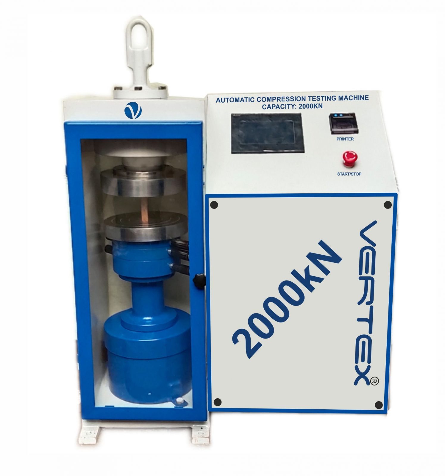
Automatic Compression Testing Machine

Manufactured as per International design, Plate model for highest mechanical stability, accurate centering of load and excellent repeatability. Fully Automatic pace rate control, auto stop and auto release on failure of test specimen, can be attached with flexural load frame or 500 KN load frame.
Semi Automatic Compression Testing Machine

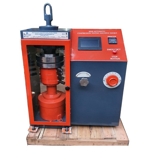
Semi Automatic Compression Testing Machine

Pace rate is achieved manually by controlling the flow control knob and the adjustment can be made by observing the error on the display and the system is released manually after the peak load is achieved.
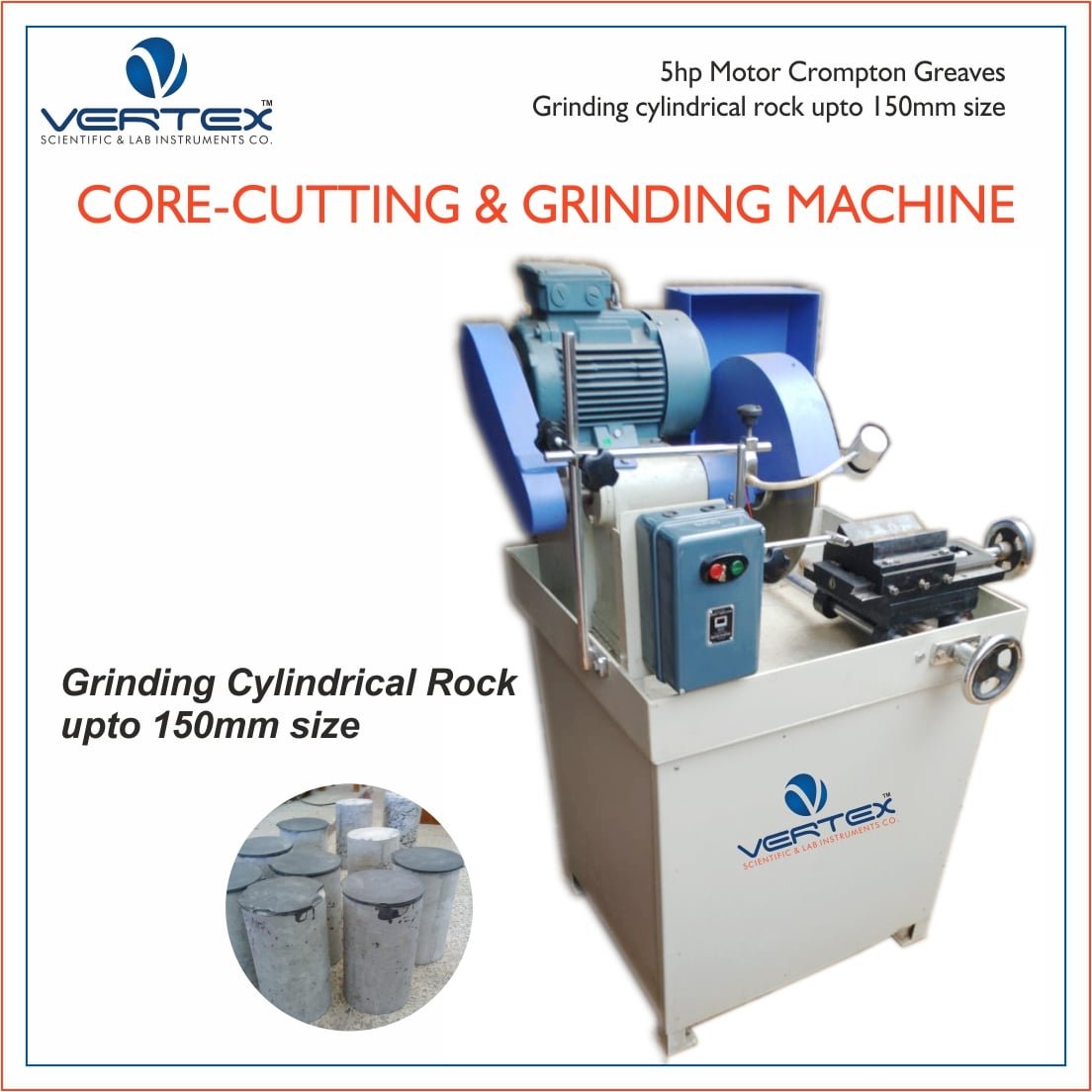
Rock Core Cutting & Grinding Machine

Rock Core Cutting & Grinding Machine

Rock Cutting Machine can be used to cut cores of varied sizes of concrete, stones, other building materials and metallic specimens.

NEW SERVO CONTROLLED COMPRESSION TESTING MACHINE