Premium Digital California Bearing Ratio-CBR Test Apparatus
VSLIC-S113
Copyright @2023 Vertex Group
Copyright @2023 Vertex Group
short info
Digital California Bearing Ratio-CBR Test Apparatus (CBR) is designed for performing laboratory evaluation of the California Bearing Ratio value of highway sub bases and subgrade and for the determination of strength of cohesive materials which have maximum particle sizes less than 19 mm (3/4”). The machine is designed to be mounted on a suitable bench and comprises of a robust and compact two column frame with adjustable upper cross beam. The frame is 50 kN capacity. Three test speeds are provided 1.25 mm/min, 1.50 mm/min & 2.5 mm/min tests. This main feature allows the user to perform tests. Laboratory California Bearing Ratio Apparatus with software & PC interface.
Standard
IS : 9669, IS : 2720 (PART XVI)
Model
VSLIC-S113
Origin
Indian
Make/ OEM
VERTEX
Warranty
This Warranty covers the defects resulting from defective parts, materials or manufacturing, if such defects are revealed during the period of 12 months since the date of purchase.
Picture
All pictures shown are for illustration purpose only. actual product may vary due to product enhancement.
Digital CBR Testing Machine is designed for performing laboratory evaluation of the California Bearing Ratio value of highway sub bases and subgrade and for the determination of strength of cohesive materials which have maximum particle sizes less than 19 mm (3/4”). The machine is designed to be mounted on a suitable bench and comprises of a robust and compact two column frame with adjustable upper cross beam. The frame is 50 kN capacity. Three test speeds are provided 1.25 mm/min, 1.50 mm/min & 2.5 mm/min tests. This main feature allows the user to perform tests. Laboratory California Bearing Ratio Apparatus with software & PC interface.
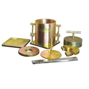
Circular Metal Spacer Disc. with Detachable Handle 148mm Dia X 47.7mm Hight
Annular Metal Weight, 2.5Kg, 147mm Dia with 53 mm Dia Central Hole
Perforated Metal Weight 2.5 Kg. 147mm Dia, with 53mm Dia Soft
Perforated Plate, 148mm Dia, with Adjustable Stem and Lock Nut
Metal Tripod for Dial Gauge
Cutting Collar
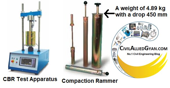
Rammer 2.6Kg, 310mm Controlled Drop
Rammer 4.9Kg, 450mm Controlled Drop
S Type Load Cell Capacity 50 kN
LVDT, 25 mm Travel, 0.01mm Least Count (Optional Extras)
FEATURES
Salient Features:
No need of separate observation on dial gauge and proving ring.
Facility to readout rate of loading in mm/minute.
Tare system to nullify initial load
The digital lcd display will retain the peak value until it is cleared.
Flow value and load on a single screen.
Flow value with a least count of 0.01 mm with accuracy of 1%.
Load value with a least count of 0.1 kg / 0.001 kn with accuracy of 1%.
Back light facility to observe the readings even in the dark.
Two line readout showing load, flow, and speed.
Software interface to PC and plot live graph.
PRODUCT VIDEO
WORKING PRINCIPALNew
California Bearing Ratio Test Procedure, CBR Test of Soil
What is California Bearing Ratio (CBR) of Soil?
California Bearing Ratio (CBR) of soil is the ratio expressed in percentage of force per unit area required to penetrate a soil mass with a standard circular plunger of 50 mm diameter at the rate of 1.25 mm/min to that required for corresponding penetration in a standard material. The ratio is usually determined for penetration of 2.5 mm and 5 mm. When the ratio at 5 mm is consistently higher than that at 2.5 mm, the ratio at 5 mm is used.
The following table gives the standard loads adopted for different penetrations for the standard material with a CBR value of 100%.
Penetration of Plunger
Standard Load
2.5 mm
1370 kg
5.0 mm
2055 kg
Note:- For Railway Formation purpose, the test is performed on remoulded specimens which are compacted dynamically.
What is California Bearing Ratio Test (CBR Test) of Soil?
The California Bearing Ratio Test (CBR Test) of soil is a penetration test developed by California State Highway Department (U.S.A.). This test is used for evaluating the bearing capacity of sub grade soil for design of flexible pavement.
IS Code for California Bearing Ratio (CBR) Test of Soil:-
IS: 2720 (Part 16): 1987; Methods of test for soils: Determination of California Bearing Ratio (second revision) of soil.
Apparatus Required for California Bearing Ratio (CBR) Test of Soil:-
Apparatus
Specification
CBR Moulds
With Base Plate, Stay Rod and Wing Nut
Cylindrical mould
Inside diameter 150 mm and height 175 mm with a detachable perforated base plate of 235 mm diameter and 10mm thickness. Net capacity will be 2250 ml; conforming to IS-9669: 1980
Collar
A detachable extension collar of 60 mm height
Spacer Disc
148 mm in diameter and 47.7 mm in height along with handle
Metal Rammer
Weight 4.89 kg with a drop 450 mm; for compaction
Expansion Measuring Apparatus
The adjustable stem with perforated plates and tripod
Weights
One annular metal weight and several slotted weights weighing 2.5 kg each, 147 mm in dia., with a central hole 53 mm in dia.
Loading Machine
With a capacity of at least 5000kg and equipped with a movable head or base which enables the plunger into penetrate into the specimen at a deformation rate of 1.25 mm/min.
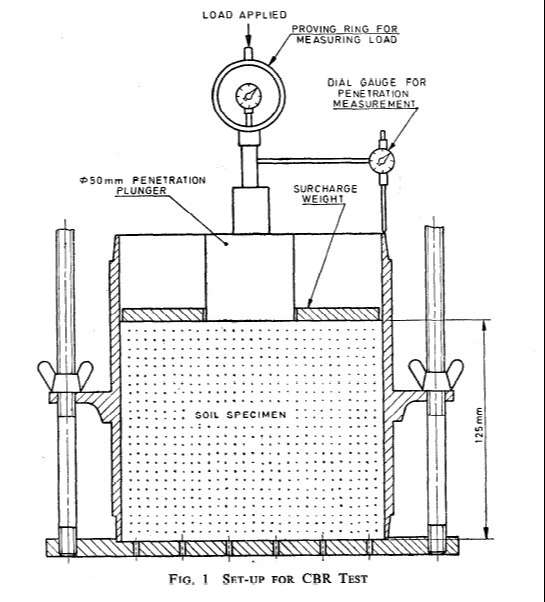
Penetration Plunger
Metal penetration piston 50 mm diameter and minimum of 100 mm in length (conforming to IS: 9669-1980)
Dial Gauges
Two dial gauges sensitive to 0.01 mm
Sieves
47.5 mm and 19 mm IS Sieves
Other apparatus
Mixing bowl, scales, straightedge, drying oven, filter paper, soaking tank or pan, dishes and calibrated measuring jar
Procedure for California Bearing Ratio Test (CBR Test) of Soil:-
Preparation of Specimens:
The CBR test of soil may be performed on undisturbed specimens or remoulded specimens which may be compacted either statically or dynamically.
Note: The static method of compaction gives the required density but requires considerable pressure and there is a possibility of the actual density varying with depth though the average density may be the one desired.
Undisturbed Specimen: Undisturbed specimen will be obtained by fitting to the mould, the steel cutting edge of 150 mm internal diameter and pushing the mould as gently as possible into the ground and digging away the soil as the mould is pushed in. When the mould is sufficiently full of soil, it will be removed by under digging, the top and bottom surface are then carefully trimmed flat so as to give the required length of specimen ready for testing. The density of the soil will be determined.
Remoulded Specimens: The dry density for a remoulding will be either the field density or the value of the maximum dry density estimated by the compaction tests.
Note: For Railway Formation, dry density is estimated by heavy compaction test as per IS: 2720: Part-8: 1983.
The water content used for compaction should be the optimum water content or the field moisture as the case may be.
Soil Sample: The test material (i.e. soil) used in the remoulded specimen should pass 19 mm IS sieve and retained on 4.75 mm IS sieve.
Statically Compacted Specimens: The mass of the wet soil at the required water content to give the desired density when occupying the standard specimen volume in the mould will be calculated. A batch of soil will be thoroughly mixed with water to give the required water content. The correct mass of the moist soils will be placed in the mould and compaction obtained by pressing in the displacer disc, a filter paper being placed between the disc and the soil.
Dynamically Compacted Specimens: For dynamic compaction, a representative sample of the soil weighing approximately 4.5 kg or more for fine-grained soil and 5.5 kg or more for granular soil will be taken and mixed thoroughly with water. If the soil is to be compacted to the maximum dry density at the optimum moisture content, the exact mass of the soil required will be taken and the necessary quantity of water added so that the water content of the soil sample is equal to the determined optimum moisture content.
Next steps:-
The mould with the extension collar attached will be clamped to the base plate and the spacer disc is inserted over the base plate.
A disc of coarse filter paper placed on the top of the spacer disc.
Lubricating oil is applied to the inner side of the mould.
The soil-water mixture will be compacted into the mould using heavy compaction. i.e. the soil is compacted in 5 layers with 55 blows to each layer by the 4.89 kg rammer.
The extension collar will then be removed and the compacted soil carefully trimmed even with the top of the mould by means of a straightedge.
Any holes developed on the surface of the compacted soil by removal of the coarse material, will be patched with the smaller size material.
The perforated base plate, the spacer disc and filter paper will be removed and the mass of the mould and the compacted soil specimen will be recorded.
A disc of coarse filter paper will be placed on the perforated base plate, the mould and the compacted soil will be inverted and the perforated base plate clamped to the mould with the compacted soil in contact with the filter paper.
In both cases of compaction, if the sample is to be soaked, representative samples of the material at the beginning of compaction and another sample of the remaining material after compaction will be taken for determination of water content. Each water content sample will weigh not less than about 50 g.
If the sample is not to be soaked, a representative sample of material from one of the cut-pieces of the material after penetration will be taken to determine the water content. In all cases, the water content will be determined in accordance with IS: 2720 (Part 2)-1973.
Procedure for Swelling Test:-
A filter paper will be placed over the specimen and the adjustable stem and perforated plate will be placed on the compacted soil specimen in the mould.
Weights to produce a surcharge equal to the weight of base material and pavement to the nearest 2.5 kg will be placed on the compact soil specimen.
The whole mould and weights will be immersed in a water tank allowing free access of water to the top and bottom of the specimen.
The tripod for the expansion measuring device will be mounted on the edge of the mould and the initial dial gauge reading recorded.
This set-up will be kept undisturbed for 96 hours noting down the readings every day against the time of reading.
A constant water level will be maintained in the tank throughout the period.
At the end of the soaking period, the change in dial gauge will be noted, the tripod removed and the mould taken out of the water tank.
The free water collected in the mould will be removed and the specimen allowed draining downwards for 15 minutes and care will be taken not to disturb the surface of the specimen during the removal of the water.
The weights, the perforated plate and the top filter paper will be removed and the mould with the soaked soil sample will be weighed and the mass recorded.
Procedure for Penetration Test:-
The mould containing the specimen, with the base plate in position but the top face exposed, will be placed on the lower plate of the penetration testing machine.
To prevent upheaval of soil into the hole of the surcharge weights, 2.5 kg annular weight will be placed on the soil surface prior to seating the penetration plunger after which the remainder of the surcharge weights will be placed.
The plunger will be seated under a load of 4 kg so that full contact is established between the surface of the specimen and the plunger.
The load and deformation gauges will then be set to zero and load is applied to the plunger into the soil at the rate of 1.25 mm per minute.
Reading of the load is taken at penetrations of 0.5, 1.0, 1.5, 2.0, 2.5, 4.0, 5.0, 7.5, 10.0 mm and 12.5 mm.
The plunger will be raised and the mould detached from the loading equipment.
About 20g to 50g of soil will be collected from the top 30mm layer of the specimen and the water content determined.
Observations and Recording:-
Recordings during CBR Test
Penetration (in mm)
Applied Load (in kg)
0.50
1.00
1.50
2.00
2.50
4.00
5.00
7.50
10.00
12.50
Calculations:-
Formula for California Bearing Ratio Test (CBR Test) of soil:-
a)
Where,
dr = final dial gauge reading in mm,
ds= initial dial gauge reading in mm and
h = initial height of the specimen in mm.
b)
Where,
PT = corrected unit (or total) test load corresponding to the chosen penetration from the load penetration curve, and
Ps = unit (or total) standard load for the same depth of penetration as for PT taken.
Report:-
The results of the California Bearing Ratio (CBR) test of soil are presented as the CBR value and the expansion ratio.
CBR of specimen at 2.5 mm penetration = …………
CBR of specimen at 5.0 mm penetration = …………
Note:- The CBR values are usually calculated for penetration of 2.5 mm and 5 mm. Generally the CBR value at 2.5 mm will be greater than at 5 mm and in such a case/the former will be taken as CBR for design purpose. If CBR for 5 mm exceeds that for 2.5 mm, the test should be repeated. If identical results follow, the CBR corresponding to 5 mm penetration should be taken for design.
Load Penetration Curve:-
The load penetration curve will be plotted (see below Fig.). This curve is usually convex upwards although the initial portion of the curve may be convex downwards due to surface irregularities. A correction will then be applied by drawing a tangent to the point of greatest slope and then transposing the axis of the load so that zero penetration is taken as the point where the tangent cuts the axis of penetration. The corrected load-penetration curve would then consist of the tangent from the new origin to the point of tangency on the re-sited curve and then the curve itself, as illustrated in below Fig.
image
Graph between Load versus Penetration.
If the initial portion of the curve is concave upwards, apply correction by drawing a tangent to the curve at the point of greatest slope and shift the origin. Find and record the correct load reading corresponding to each penetration.
Get Instant Quote
Our Hot Selling Instrument's
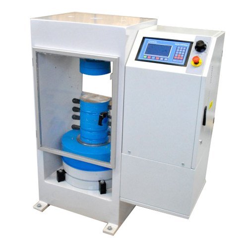
Servo Fully Automatic Compression Testing Machine
One of the key advantages of the SERVO CONTROLLED FULLY AUTOMATIC COMPRESSION TESTING MACHINE is its ability to deliver highly accurate results. This precision ensures that your materials meet the required standards, reducing the risk of costly errors and rework. Moreover, by producing consistent and reliable outcomes, you build a reputation for quality in your industry.
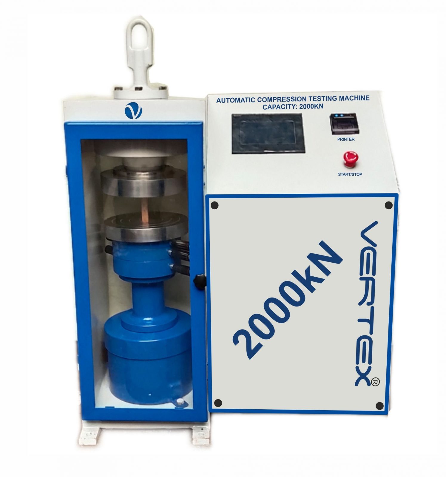
Automatic Compression Testing Machine
Manufactured as per International design, Plate model for highest mechanical stability, accurate centering of load and excellent repeatability. Fully Automatic pace rate control, auto stop and auto release on failure of test specimen, can be attached with flexural load frame or 500 KN load frame.
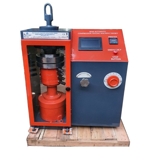
Semi Automatic Compression Testing Machine
Pace rate is achieved manually by controlling the flow control knob and the adjustment can be made by observing the error on the display and the system is released manually after the peak load is achieved.
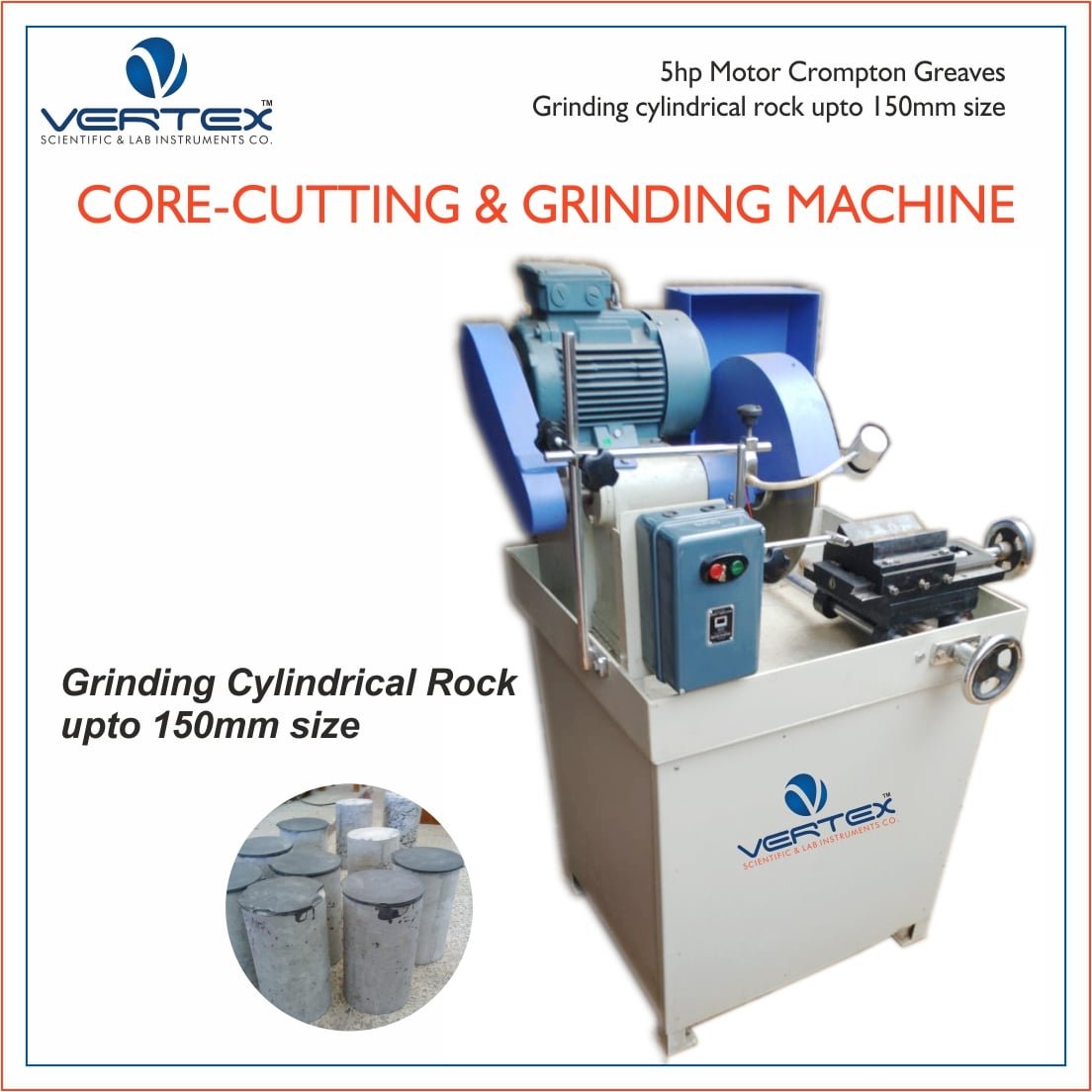
Rock Core Cutting & Grinding Machine
Rock Cutting Machine can be used to cut cores of varied sizes of concrete, stones, other building materials and metallic specimens.